
BY ORDER OF THE
SECRETARY OF THE AIR FORCE
AIR FORCE MANUAL 11-2KC-10 VOLUME 3 ADDENDA-A
8 APRIL 2019
Flying Operations KC-10 AIRCRAFT CONFIGURATION
![]()
![]()
OPR: AMC/A3V
Supersedes: AFI11-2KC- 10V3_ADDENDA-A, 17 January 2012
Certified by: AF/A3T (Maj Gen Scott F. Smith)
Pages: 23
![]()
This manual implements Air Force Policy Directive (AFPD) 11-2, Aircraft Rules and Procedures, and is incomplete without Air Force Manual (AFMAN) 11-2KC-10 Volume 3, KC-10 Operations Procedures. It establishes policy for the configuration of the KC-10 aircraft to safely and successfully accomplish their worldwide mobility missions. This is a specialized publication intended for use by Airmen who have graduated from technical training related to this publication. This manual applies to all commanders, operations supervisors, and aircrew assigned or attached to all flying activities of commands operating KC-10 aircraft. It applies to Air Force Reserve units, but does not apply to the Air National Guard (ANG). Ensure all records created as a result of processes prescribed in this publication are maintained in accordance with AFMAN 33-363, Management of Records, and disposed of in accordance with the Air Force Records Disposition Schedule located in the Air Force Records Information Management System. This Manual requires the collection and or maintenance of information protected by the Privacy Act of 1974 authorized by Title 5 United States Code, Section 552a, as amended, and Executive Order 9397, Numbering System for Federal Accounts Relating to Individual Persons, as amended. The applicable SORN F011 AF XO A, Aviation Resource Management Systems is available at: http://dpclo.defense.gov/Privacy/SORNs.aspx. Refer recommended changes and questions about this publication to the Office of Primary Responsibility (OPR) using the AF IMT 847, Recommendation for Change of Publication; route AF IMT 847s from the field through the appropriate functional’s chain of command. The use of the name or mark of any specific
manufacturer, commercial product, commodity, or service in this publication does not imply endorsement by the Air Force.
SUMMARY OF CHANGES
This document has been substantially revised and needs to be completely reviewed. Major changes include re-designation as AFMAN; clarifies maintenance responsibilities concerning bunks and cargo barrier net (para 1.13); added “Paint/Depot” column in Table 1.1; updated Notes and added requirements for Item 60 (Table 1.1); updated requirements in Table 1.2.
Chapter 1— KC-10 AIRCRAFT CONFIGURATION
1.18. KC-10 Cargo Door Safety Net. .............................................................................. 19
Table 1.3. KC-10 Cargo Door Safety Net................................................................................ 19
Attachment 1— GLOSSARY OF REFERENCES AND SUPPORTING INFORMATION
This chapter establishes basic planning factors to be used by planners, maintainers and operators at all levels of command and directs KC-10 aircraft configuration for local or training missions, worldwide missions and contingency operations, and CAPSTONE/DV missions. KC-10 aircraft may also be configured in accordance with governing operations order (OPORD) or fragmentation (FRAG) order.
Roles and Responsibilities are found within each section of this Addenda.
All units and agencies involved in preparing KC-10 aircraft for deployment in support of contingency and other operations will use this chapter. (T-3)
This chapter is applicable to all units operating or supporting KC-10 aircraft and provides mandatory standard configuration guidance.
Missions may be of short duration with immediate return to home station, or be to a specific location for an extended period of time to provide air refueling and airlift support for general purpose forces and strategic conventional forces. Subordinate commanders must be prepared to deploy KC-10 aircraft, associated equipment, personnel, and materials. (T-3)
Normal configuration for local or training missions should be code “B” or code “J”.
All aircraft will be configured for deployment as required by implementing FRAG or OPORD. (T-3)
The unit will use the configuration checklists approved by HQ AMC/A4M. (T-3) Checklist distribution will be made to all agencies involved with the actual aircraft configuration. (T-3)
After configuration has been determined, the Production Superintendent will be the single point of contact to ensure required configuration actions are complete.
Proper aircraft configuration is the responsibility of the pilot in command.
En Route Support Kits (ESK) or Mission Support Kits (MSK) will be carried when required, as outlined in each aircraft configuration. (T-3)
On a temporary basis, additional equipment may be required to satisfy mission requirements. When required, the tasked unit must assure that coordination includes appropriate functional areas and that additional equipment is onboard. (T-3)
Weight and Balance. Unit weight and balance personnel will ensure accuracy and currency of DD Form 365-3; Chart C - Basic Weight and Balance Record. When aircraft are changed from daily configuration code B or J to another standard configuration, the change will be reflected on Form F by the Boom Operator. If a nonstandard configuration is required, the weight and balance data will be provided by the local configuration checklist. (T-3)
In the remarks section of an airlift request, users will supply cargo loading equipment information (e.g. pallet sub-floor requirements, winch, chains, devices, etc.). The additional cargo loading equipment type and quantity will be annotated in the Global Decision Support System (GDSS). (T-3)
Aerial Port personnel will deliver and load cargo handling equipment in excess of that is required to be maintained onboard aircraft daily. This includes all aircraft pallet equipment. (T-3)
Cargo missions originating at the main operating base (MOB) will be load planned by the transportation unit in coordination with the wing current operations. Re-deployment load planning will be the responsibility of the unit movement officer. (T-3)
Configuration waivers are needed any time equipment is placed in aisle spaces, equipment that hinders access to emergency equipment/oxygen, aircraft seats installed facing aft, and the cargo handling system used not as designed (e.g. moving rails, latch pawls, etc.). This list is not comprehensive or all inclusive. A waiver is required anytime a piece of equipment is installed in a place it was not designed for, or if it will hinder evacuation of the aircraft. The addition of equipment that is not listed in DD Form 365-1, Chart A - Basic Weight Checklist Record, that has not been tested or certified for use in the KC-10 also constitutes a nonstandard configuration. Units will request a waiver from MAJCOM A3 for any departure from the standard configurations. Approved distinguished visitor (DV) configurations will not require special waivers. (T-3)
If an Increased Accommodation Unit (IAU) or extra IAU is to be carried from one point to another, it may be carried as aircraft equipment. The left side outboard restraint rails can be moved to their outboard positions, and the IAU positioned down the left side of the aircraft. The seats will not be occupied during takeoff, landing, or flight. (T-2) No waiver is required.
Senior Leader In-Transit Conference Capsule (SLICC). SLICC includes: palletized conference module, palletized berthing module, a transit case for each module and 75 or 16 seats. Seat availability will be dictated by mission requirements. The SLICC is a deployable 463L-compatible pallet that provides temporary first-class palletized seating for senior level personnel to utilize when traveling on other than Operational Support Airlift or Special Air Mission aircraft. The SLICC will only be loaded on Command and Control Module equipped aircraft. (T-3) The conference and berthing module will not be occupied during takeoff, tanker/receiver air refueling, approach, or landing. (T-3) Procedures for installing the module are in Section 5 of T.O. 1C-10(K)A-9.
The conference module contains two seats, a divan, work tables and audio/visual equipment. The berthing module contains two bunk beds and stowage compartments. The conference and berthing modules may be carried together or separately. The conference module has the capability to carry up to 5 personnel and the berthing module has the capability to carry up to 2 personnel. When cleared by the Pilot In Command (PIC) the crew chief and boom operator or flight attendants (FAs) will proceed to the module after take-off, establish power application, and establish interphone contact with the cockpit. Once interphone contact has been established, additional personnel will be cleared to the module. The right side section of the environmental curtain and cargo barrier net should be stowed to allow easy access to the module after passing 10,000 feet MSL and reinstalled after the module has been cleared prior to final landing. Interphone contact will be established and maintained with the module operator anytime the module is occupied.
The SLICC requires 7 Emergency Passenger Oxygen System (EPOS) units. In the event of a loss of cabin pressurization all occupants of the module will don the EPOS and proceed to the forward cabin when directed by the AC or a uniformed flight crewmember. Once seated in the forward cabin, they should be directed to use the drop- down masks as required.
The aircraft commander retains overall authority to remove personnel from the SLICC when passenger safety may be jeopardized (in-flight emergency, combat threat environments etc.). Aircraft commanders will be responsible to ensure that the user of the SLICC is briefed prior to the mission on the takeoff, air refueling and landing occupancy restrictions as well as the potential for removal from the SLICC should flight conditions warrant. (T-3)
If FAs accompany the SLICC, they will manage the DV and accompanying party. When reporting for the mission, they will provide the PIC with a current ground training report and copy of the most current AF Form 8 certifying that they are current and qualified to operate equipment on the KC-10. FAs are qualified to operate doors (normal and emergency operation), brief and monitor passengers, accomplish customs and border clearance, and operate emergency equipment located in the forward cabin and cargo compartment. The lead FA will coordinate duties with the senior Boom Operator before the mission. Management of the DV and party is the primary responsibility of the senior FA; however, the overall responsibility of managing the forward cabin and cargo compartment rests with the senior Boom Operator on board the aircraft. (T-3)
When transported as unoccupied cargo, no electrical connections shall be made for SLICC and the extendable breezeway shall be stowed. (T-2)
Senior Leader In-Transit Pallet (SLIP) Configuration. The SLIP configuration is a modified delta configuration. The weight and balance information for this configuration is provided to enable the Boom Operator to make a one line entry on the DD Form 365 - 4 Form F to account for the equipment. Each affected agency involved in the configuration change is responsible for ensuring correct installation of equipment.
Pallet position 2R will contain the SLIP. Pallet position 3R will contain an empty pallet. Pallet position 2L will contain an IAU pallet with the seats removed. Pallet position 3L IAU seat pallet is unchanged, but the four front row seats will not be occupied during flight. The walkway will be installed along the aircraft right side up to the IAU cabinets. A modified panel is required to be installed in front of door 2R. Four EPOS are required to be placed in the SLIP and will be the primary emergency oxygen source for personnel occupying the seats. (T-2)
Boom Operators will subtract (-) 357 pounds and a moment of (-) 33 from the Form F. (T-3)
DV 1 Configuration. The weight and balance information for this configuration is provided to enable the Boom Operator to make a one line entry on the DD Form 365 - 4 Form F to account for the equipment. Each affected agency involved in the configuration change is responsible for ensuring correct installation of equipment. The Production Superintendent will be the single point of contact to ensure required configuration actions are complete. Install two executive tables. The first one is installed between seat row 1 and 2 center. Seat row 1C is turned 180 degrees and seat row 2C is relocated aft at station 528. The second table is located at station 563 after removal of seat row 3R. The following restrictions apply: NOTES: 1. Aft facing seats (row 1C) will not be occupied for takeoffs and landings. (T-3) 2. Drop down oxygen must be readily available. (T-3) 3. Install a tabletop on the bunks. Nothing will be placed on the table for takeoff or landing. 4. Install a carpeted plywood walkway from pallet position 4R through 9R.
Maintenance, Dash 21, and Special Mission’s Airlift, will configure the aircraft in the following manner for DV Configurations: Add item C- 163 DV Buffet Table on top of lower bunks at station # 869. Add item C- 82.1 Forward Double Center Seat to a new position at station 462. Add item C- 83.1 Aft Double Center Seat to a new position at station # 528. Add item C- 83.2 DV Table, center aisle at station # 494. Add item C-87.1 DV Table right side of fuselage at station #563. Add item C -202.1 Plywood Walkway right side of fuselage station 1194. Remove item C-87 Right side double seat for DV table at station #551. Remove item C- 0 Conveyors and walkway, right side of fuselage.
Boom Operators will add (+) 121 Pounds at a moment of (+) 4.3 to the Form F.
DV 2 Configuration. DV 2 Configuration is the same as DV 1 Configuration without the removal of the conveyors and walkway, and without the installation of the plywood walkway. Boom Operators will add (+) 221 Pounds at a moment of (+) 16.2 to the Form F. (T- 3)
DV 3 Configuration. DV 3 Configuration is the same as DV 1 Configuration without the removal of the conveyors and walkway, and without the installation of the plywood
walkway and Buffet table. Boom Operators will add (+) 81 Pounds at a moment of (+) 4.1 to the Form F. (T-3)
DV 4 Configuration. DV 4 Configuration is a 16 seat configured aircraft with one executive table The table is installed between seat row 1 and 2 center. Seat row 1C is turned 180 degrees and seat row 2C is relocated aft at station 528. The aft facing seats (row 1C) will not be occupied for takeoffs and landings and drop down oxygen must be readily available. Boom Operators will add (+) 80 Pounds at a moment of (+) 4.1 to the Form F. (T-3)
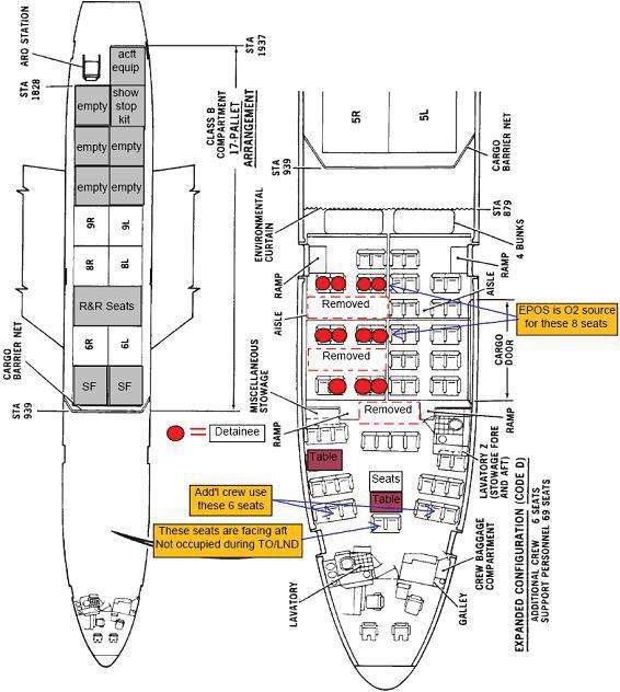
Detainee Configuration (DTC). DTC is a modified DV 3 configuration. Aircraft Weight and Balance personnel will update and provide the Boom Operator with updated DD Form 365-3; Chart C - Basic Weight and Balance Record, detailing the configuration change. (T-3) A Detainee Movement guide is provided at https://cs2.eis.af.mil/sites/12679/Aircrew%20Pubs%20Library/Master_Library_Verifie d/KC10/detainee_movement_guide.pdf#search=Detainee
Eleven detainees will be seated as depicted on the seating diagram in Figure 1.1. The canon plugs will be disconnected for the right side IAU seat pallets. EPOS will be the primary emergency oxygen source for personnel occupying those seats. Security Forces (SF) personnel will don their EPOS hood prior to assisting detainees. SF personnel will be responsible for donning of detainees’ EPOS hood. Removed set of quad seats will be stored on a pallet during detainee mission (including positioning leg). After completion of detainee mission, seats will be reinstalled. (T-3)
Two side facing seat pallets will be loaded in pallet positions 7 L/R. These seats are for Security Forces (SF) for in-flight rest. If these seat pallets are not available, an additional IAU seat pallet (preferably one that fits in pallet position 3 L) will be loaded in pallet position 7 L for SF in-flight rest (7 R will be an empty pallet position). The side facing seats in the cargo compartment are for SF personnel to use for in-flight rest. These seats will not be occupied for takeoff and landing (including additional IAU seat pallet in their stead). SF personnel will be cleared by the Boom Operator prior to proceeding aft of the environmental curtain. EPOS will be the primary emergency oxygen source for personnel occupying these seats. The Boom Operator will ensure that EPOS is located at each seat. SF personnel will maintain interphone contact with the pilot at all times when the seats are occupied. (T-3)
After completion of the detainee mission, normal rules apply. Maintenance personnel will reinstall the quad row of seats. These seats may be needed to move additional SF personnel back to the CONUS. The right side seat pallets will remain disconnected and will not be occupied during flight. The side facing seat pallets in the cargo compartment will not be occupied during flight. All passenger seating will be at the discretion of the Pilot in Command. (T-3)
Logistics Plans. The unit logistics plans function will be the single focal point for all logistics support planning for deployment operations. They will maintain close coordination with the unit operations plans function and all logistics functions to ensure all logistics support requirements are met. (T-3) Obtain specific support capabilities available at deployment location and relay this information to maintenance and operations plans to be used during
mission support planning. Monitor all deployments to ensure adequate support is provided or drawn from the functional areas tasked.
The operations group will provide the logistics plans function with information pertaining to aircraft configuration. (T-3)
Supply. KC-10 supply support is provided primarily by civilian contractor logistics support system represented at base level by the Contractor-Operated and Maintained Base Supply (COMBS). The COMBS manager must be made aware of the following information for all deployments away from the MOB to ensure appropriate range and quantity of items are included in the onboard support kit: Date and length of deployment, number of aircraft involved, number of sorties and flying hours planned, location of FOL, and peculiar support equipment requirements. (T-3) NOTE: If security considerations preclude the COMBS manager from access to any of the above information, he or she must be made aware of appropriate supply levels and military port where material is to be shipped. (T-3)
Logistics Support Contractor (LSC). LSC is responsible for assembly of ESKs and MSKs. Quantities in kits may vary based on mission requirements. Maintenance will provide information required and work with COMBS manager to determine spares requirements. (T- 3)
Senior Maintenance Supervisor. The senior maintenance supervisor is responsible for the deployed support kit and deployed support equipment. If required, contractor personnel may be deployed to manage the support kit at the FOL. These personnel must have valid security clearances and passports as required by KC-10 logistics support contracts. (T-3) The designated kit manager will accept accountability prior to deployment. (T-3)
Items not available in the deployed kit. Contractor managed parts causing a not mission-capable supply status or partial mission-capable status on a Tanker Airlift Control Center (TACC) controlled mission will be relayed through AMC/XOCL to the MOB maintenance operations center (MOC). The MOB MOC will relay requirements to production supervisors who will coordinate the requirements with the COMBS. COMBS supporting units not on TACC missions (CHOPPED) will directly contact the supporting MOB COMBS. Re-supply of ESKs and MSKs will be handled through AMC/TACC/XOCL. (T-2)
Aircrew Flight Equipment Accountability. Accountability of prepositioned Aircrew Flight Equipment will be the responsibility of the PIC and may be delegated to any member of the primary flight crew. Document equipment inventories on the AFTO Form 46, Prepositioned Aircrew Flight Equipment
Status reporting will be in accordance with Air Force Instruction (AFI) 21-103, Equipment Inventory, Status and Utilization Reporting. Aircraft possession will not normally be transferred to an operating location. (T-2)
Aircraft selected for deployment should be identified as early as possible. Selection should be based on present and past performance and known scheduled maintenance and depot requirements.
C-Check and paint (depot) schedules are planned and accomplished by the logistic support contractor. Aircraft deployed will be replaced in order to make scheduled depot input. If the aircraft cannot be replaced it must be returned for depot. Operational requirements will not interrupt the depot schedule. (T-3)
Aircraft will not deploy with an engine that requires removal for expiration of maximum operating time or reconditioning interval during deployment tasking. (T-3)
Spare engines will not be deployed unless specified in the implementing FRAG order.
Units will send an adequate supply of engine conditioning coupons per aircraft to cover the entire deployment. (T-3)
One complete set of technical orders for the aircraft (electronic or hardcopy) will be deployed to support FOL operations. Technical order requirements (electronic or hardcopy) for other than FOL operations will be determined by the MOB. (T-3)
For a local training mission, maintenance personnel are not normally required.
Deploying personnel will comply with the requirements in AFI 10-403, Deployment Planning and Execution, and the Installation Deployment Plan. (T-3)
Deploying personnel must be qualified in accordance with AFI 21-101, Aircraft and Equipment Maintenance Management or appropriate MAJCOM guidance. (T-2)
When deemed necessary by the MXG commander, contractor personnel may be deployed. Deployment onboard United States Air Force aircraft is authorized.
TACC staff will contact the aerial port squadron transportation function with long range (30 days when available) mission schedule configuration requirements to facilitate coordination for manpower and equipment support. (T-3)
Base transportation squadrons or aerial port squadrons (where assigned) are responsible for installation or removal of pallet sub-floors without restriction, and storage or accountability for operational system 463L cargo pallets, nets, and tie-down devices.
Transportation and aerial port load team personnel may conduct loading and unloading of aircraft support equipment (i.e. tow bars, ESK, etc.) without supervision after coordinating with the KC-10 Boom Operator. The types of KC-10 support equipment that will be loaded or unloaded without supervision will be fully coordinated between transportation, the aerial port, and operations, and a resulting list will be provided. (T-3) To preclude problems with aircraft tip-over as a result of exceeding station arm 1430, no cargo will be loaded aft of pallet position 8 or station 1393.
Passenger processing (which includes booking, check-in, anti-theft and anti- hijacking procedures, baggage weighing, tagging and loading, and manifesting and boarding passengers) will be accordance with AMCI 24-101, Volume 14 Military Airlift—Passenger Services, and this instruction. Mobility deployments will be in accordance with base mobility plan. (T-2)
TACC staff will manage cargo loaders assigned to AMC in support of KC-10 operations. The TACC will determine need for and coordinate movement of equipment and personnel to assemble or disassemble and operate cargo loaders in support of KC-10 operations at other than home station. Units will contact the TACC if operations dictate the need for deployed wide-body loader support. The KC-10 on-board loader will be operated and assembled by Aerial Port personnel. (T-3)
AMC4128, Fleet Service Checklist, will be utilized by the transportation function to control support equipment placed onboard aircraft. Add any items peculiar to the station or flight in the blank space provided (i.e. KC-10 pallet couplers, chains, straps, devices, and passenger comfort items.) AMC4128 will be completed in accordance with AMCI 24-101, Volume 10 Military Airlift—Fleet Service. (T-2)
Code A: Pallets - 23, Seats - 14, Maximum cargo load - 175,000 lb.
Code A-1: Pallets - 23, Seats - 14, Maximum cargo - 175,000 lb. Pallet 13L is reserved for aircraft equipment, support equipment, and baggage. 3 seats are reserved for crew chiefs, support personnel, or extra crew members.
Code A-2: Pallets - 23, Seats - 14, Maximum cargo - 175,000 lb. Pallets 12L and 13L are reserved for aircraft equipment, support equipment, and baggage. 4 seats are reserved for crew chiefs, support personnel, or extra crew members.
Code A-3: Pallets - 23, Seats - 14, Maximum cargo - 175,000 lb. Pallets 11L, 11R, 12L, 12R, and 13L are reserved for aircraft equipment, support equipment, and baggage. 14 seats are reserved for crew chiefs, support personnel, or extra crew members.
Code B: Pallets - 23, Seats - 16, Maximum cargo - 100,000 lb.
Code B-1: Pallets - 23, Seats - 16, Maximum cargo - 100,000 lb. Pallet 13L is reserved for aircraft equipment, support equipment, and baggage. 3 seats are reserved for crew chiefs, support personnel, or extra crew members.
Code B-2: Pallets - 23, Seats - 16, Maximum cargo - 100,000 lb. Pallets 13L and 12L are reserved for aircraft equipment, support equipment, and baggage. 4 seats are reserved for crew chiefs, support personnel, or extra crew members.
Code B-3: Pallets - 23, Seats - 16, Maximum cargo - 100,000 lb. Pallets 11L, 11R, 12L, 12R, and 13L are reserved for aircraft equipment, support equipment, and baggage. 16 seats are reserved for crew chiefs, support personnel, or extra crew members.
Code C: Pallets - 23, Seats - 20, Maximum cargo weight on each pallet - 2,100 pounds.
Code C-1: Pallets - 23, Seats - 20, Maximum cargo weight on each pallet - 2,100 pounds. Pallet 13L is reserved for aircraft equipment, support equipment, and baggage. 4 seats are reserved for crew chiefs, support personnel, or extra crew members.
Code C-2: Pallets - 23, Seats - 20, Maximum cargo weight on each pallet - 2,100 pounds. Pallets 13L and 12L are reserved for aircraft equipment, support equipment, and baggage. 4 seats are reserved for crew chiefs, support personnel, or extra crew members.
Code C-3: Pallets - 23, Seats - 20, Maximum cargo weight on each pallet - 2,100 pounds. Pallets 11L, 11R, 12L, 12R, and 13L are reserved for aircraft equipment, support equipment, and baggage. 6 seats are reserved for crew chiefs, support personnel, or extra crew members.
Code C-4: Pallets - 23, Seats - 20, Maximum cargo weight on each pallet - 2,100 pounds. Pallets 11L, 11R, 12L, 12R, and 13L are reserved for aircraft equipment, support equipment, and baggage. 8 seats are reserved for crew chiefs, support personnel, or extra crew members.
Code C-5: Pallets - 23, Seats - 20, Maximum cargo weight on each pallet - 2,100 pounds. Pallets 11L, 11R, 12L, 12R, and 13L are reserved for aircraft equipment, support equipment, and baggage. 10 seats are reserved for crew chiefs, support personnel, or extra crew members.
Code C-6: Pallets - 23, Seats - 20, Maximum cargo weight on each pallet - 2,100 pounds. Pallets 11L, 11R, 12L, 12R, and 13L are reserved for aircraft equipment, support equipment, and baggage. 20 seats are reserved for crew chiefs, support personnel, or extra crew members.
Code D: Pallets - 17, Seats - 75, Maximum cargo load - 145,500 lb.
Code D-1: Pallets - 17, Seats - 75, Maximum cargo load - 145,500 lb. Pallet 13L is for reserved aircraft equipment, support equipment, and baggage. 3 seats are reserved for crew chiefs, support personnel, or extra crew members.
Code D-2: Pallets - 17, Seats - 75, Maximum cargo load - 145,500 lb. Pallets 12L, 12R, and 13L are reserved for aircraft equipment, support equipment, and baggage. 3 seats are reserved for crew chiefs, support personnel, or extra crew members.
Code D-3: Pallets - 17, Seats - 75, Maximum cargo load - 145,500 lb. Pallets 11L, 12L, 12R, and 13L are reserved for aircraft equipment, support equipment, and baggage. 4 seats are reserved for crew chiefs, support personnel, or extra crew members.
Code D-4: Pallets - 17, Seats - 75, Maximum cargo load - 145,500 lb. Pallets 10L, 10R, 11L, 11R, 12L, 12R, and 13L are reserved for aircraft equip, support equip, and baggage. 6 seats are reserved for crew chiefs, support personnel, or extra crew members.
Code D-5: Pallets - 17, Seats - 75, Maximum cargo load - 145,500 lb. Pallets 10L, 10R, 11L, 11R, 12L, 12R, and 13L are reserved for aircraft equip, support equip, and baggage. 8 seats are reserved for crew chiefs, support personnel, or extra crew members.
Code G: Pallets - 17, Seats - 20, Maximum cargo load - 145,500 lb. Cargo barrier net at position 3 (station 939). Environmental curtain and bunk at position 2 (station 576).
Code J: Pallets - 17, Seats - 31, Maximum cargo load –1000 lbs. (Aircraft Equipment). Cargo barrier net at position 3 (station 939). Environmental curtain at (station 879) and bunks at (station 869). Modified Code D configuration with all four IAU seat pallets removed but Z Lav, IAU storage, track mounted seats, emergency oxygen and exit signs still installed. For local mission or deployed locations only. CAUTION: Use caution when transiting the exposed omni panel area in the Code J configuration. Exposed omni panel rollers, latch pawls and power roller wells pose an increased tripping/fall hazard. CAUTION: Passengers and cargo will not be carried in the Code J configuration. (T-3)
All deviations (more or less) from item quantities listed in Tables 1.1 and 1.2 require coordination and approval by the PIC and the Maintenance Production Superintendent. For deviations below the minimums listed in Tables 1.1 and 1.2, see paragraph 1.17.2. Missing and/or excess items affecting aircraft weight and balance will be accounted for on the DD Form 365-4, by the Boom Operator. Any missing items must also be documented in the aircraft forms. (T-3)
Waiver Protocol. For aircraft operation with less than the minimum equipment requirements listed in Tables 1.1 and 1.2, refer to MEL waiver protocol in AFMAN 11-2KC- 10 Volume 3, KC-10 Operations Procedures, Chapter 4.
Line Number | NOMENCLATURE | TYPE MISSION | NOTES | |||
Local Trainer | CONUS | OCONUS/ DV | Paint/ Depot | |||
1. | AFTO Form 781, ARMS Aircrew /Mission Flight Data Document | As Required | As Required | As Required | As Required | |
Line Number | NOMENCLATURE | TYPE MISSION | NOTES | |||
Local Trainer | CONUS | OCONUS/ DV | Paint/ Depot | |||
2. | ECMP coupon book | 1 | 1 | 1 | 1 | |
3. | Appropriate debriefing form | As Required | As Required | As Required | As Required | |
4. | Spare AFTO 781 Series forms | As Required | As Required | As Required | As Required | |
5. | DD 1896, Jet Fuel Identa-plate | 1 | 1 | 1 | 1 | |
6. | DD 365-4, Weight and Balance Clearance Form F - Transport | 1 | 1 | 1 | 0 | |
7. | T.O. 1-1B-50 Manual of Weight and Balance | 1 | 1 | 1 | 0 | 4 |
8. | T.O. 1C-10(K)A-06, Work Unit Code Manual | 1 | 1 | 1 | 0 | 4 |
9. | T.O. 1C-10(K)A-2-7CL-1, Jacking Checklist | 1 | 1 | 1 | 0 | 4 |
10. | T.O. 1C-10(K)A-2-9CL-1, Towing Checklist | 1 | 1 | 1 | 0 | 4 |
11. | T.O. 1C-10(K)A-2-12, Servicing | 1 | 1 | 1 | 0 | 4 |
12. | T.O. 1C-10(K)A-2-12-1, Potable Water Service | 1 | 1 | 1 | 0 | 4 |
13. | T.O. 1C-10(K)A-2-12-2, Hydraulic Service | 1 | 1 | 1 | 0 | 4 |
14. | T.O. 1C-10(K)A-2-12-3, Waste Water Service | 1 | 1 | 1 | 0 | 4 |
15. | T.O. 1C-10(K)A-2-12-4, Constant Speed Drive Service | 1 | 1 | 1 | 0 | 4 |
16. | T.O. 1C-10(K)A-2-12-5, Engine Oil Service | 1 | 1 | 1 | 0 | 4 |
17. | T.O. 1C-10(K)A-2-12CL-1, Refuel/De-fuel Check-list | 1 | 1 | 1 | 0 | 4 |
18. | T.O. 1C-10(K)A-2-12CL-2, Oxygen Service | 1 | 1 | 1 | 0 | 4 |
19. | T.O. 1C-10(K)A-2-24-1, External Electrical Power | 1 | 1 | 1 | 0 | 4 |
20. | T.O. 1C-10(K)A-2-25CL-1, IAU Installation/Removal | 1 | 1 | 1 | 0 | 4 |
21. | T.O. 1C-10(K)A-2-32CL-1, Landing Gear | 1 | 1 | 1 | 0 | 4 |
22. | T.O. 1C-10(K)A-2-28CL-1, Boom/Drogue Ground Operations | 1 | 1 | 1 | 0 | 4 |
23. | T.O. 1C-10(K)A-2-36-1, External Pneumatic Power | 1 | 1 | 1 | 0 | 4 |
24. | T.O. 1C-10(K)A-2-49CL-1, Airborne Auxiliary Power Unit | 1 | 1 | 1 | 0 | 4 |
25. | T.O. 1C-10(K)A-2-71CL-1, Power Plant Ground Operations | 1 | 1 | 1 | 0 | 4 |
26. | T.O. 1C-10(K)A-6WC-1, Pre-flt, Basic Post-flt and Thru-flt Inspection Work Cards | 1 | 1 | 1 | 0 | 4 |
Line Number | NOMENCLATURE | TYPE MISSION | NOTES | |||
Local Trainer | CONUS | OCONUS/ DV | Paint/ Depot | |||
27. | T.O. 1C-10(K)A-6WC-6, Special Inspection Work cards | 1 | 1 | 1 | 0 | 4 |
28. | T.O. 1C-10(K)A-1-2, Minimum Equipment List | 1 | 1 | 1 | 1 | 4 |
29. | Cover assembly, pitot tube | 3 | 3 | 3 | 3 | |
30. | Lock assembly, nose landing gear, PN7000-501 | 1 | 1 | 1 | 1 | |
31. | Lock assembly, centerline landing gear, PN53719, “L” | 1 | 1 | 1 | 1 | |
32. | Lock assembly, main landing gear door open, DZZ7044-1 | 2 | 2 | 2 | 2 | |
33. | Lock assembly, main landing gear, PN7000-501 | 2 | 2 | 2 | 2 | |
34. | Ground wires (50 ft.), 4010-00- 268-2681 | 0 | 0 | 2 | 0 | |
35. | Sill Protector, Cargo door, A227475-503 | 1 | 1 | 1 | 1 | |
36. | Chocks (30 inches long) | 4 | 4 | 4 | 0 | |
37. | Cover assembly, engine inlet, TS- 1079W | 3 | 3 | 3 | 3 | 6 |
38. | Cover assembly, engine exhaust | As Required | As Required | 3 | 0 | 6 |
39. | Ladder, Little Giant, 5410-01-092- 1894 | As Required | 1 | 1 | 0 | |
40. | Oil, Mobile Jet II (case), 9150-00- 913-9717 | 1 | 1 | 1 | 0 | |
41. | Skydrol (case), 9150-00-485-0075 | 1 | 1 | 1 | 0 | |
42. | Hydraulic spray (can), 9150-00- 159-4472 | As Required | 1 | 1 | 0 | |
43. | Bucket, 7240-00-943-4472 | As Required | 1 | 1 | 0 | 5 |
44. | Headset, 1212G-12 | As Required | As Required | 1 | 0 | |
45. | Extension cord, CE394L8M25 | As Required | As Required | 1 | 0 | |
46. | Eye goggles | 1 | 1 | 1 | 0 | |
47. | Eye saline eyewash (bottle), 4630, 3b | 6 | 6 | 6 | ||
48. | Oil service unit, 53361-7 | 1 | 1 | 1 | 0 | |
49. | CGU-1/B or MC-1 nylon strap, 5000 pound capacity | 30 | 30 | 30 | 1 | |
50. | MB-1 tiedown chain, MIL-T 29559, 1670-00-516-8406 | 30 | 30 | 30 | 1 | |
51. | MB-1 tension device, MIL-T- 25959, 1670-00-212-1149 | 30 | 30 | 30 | 0 | 1,7 |
Line Number | NOMENCLATURE | TYPE MISSION | NOTES | |||
Local Trainer | CONUS | OCONUS/ DV | Paint/ Depot | |||
52. | Pallet coupler, 1-inch | 6 | 6 | 6 | 0 | |
53. | Anti-freeze (gallons) | 0 | As Required | As Required | As Required | |
54. | Barrier assembly, cargo door, local manufacture | 1 | 1 | 1 | 1 | |
55. | Fitting, cargo, A7000, 1760-00- 463-7478 | 12 | 12 | 12 | 0 | |
56. | IAU Seat Pallets | 0 | As Required | As Required | As Required | |
57. | JA/ATT Box | 0 | As Required | As Required | 0 | |
58. | Cargo Winch | 0 | As Required | As Required | 0 | 2 |
59. | Pallet 13L, Pallet subfloor | 1 | 1 | 1 | 0 | 3 |
NOTES: | ||||||
If specific mission requirements dictate, quantities may be increased for straps-up to 100, Chains -150, and tension devices-150.
Will be stored in the floor at station 1856, or restrained on a 463L pallet when mission requirements dictate. The weight of 88 pounds will be annotated on the Form F. (T-3)
Stowage pallet is not considered cargo.
May be either electronic or hardcopy.
Dispatch with less than the minimum quantities listed only requires coordination/approval by the PIC and the Maintenance Production Superintendent. No waiver required.
Required for cold weather operations.
The CGU-8/A Aircraft Chain Tensioner can be used and will replace the MB-1 & CGU-4/E Chain Tensioners. The old 10K Aircraft Cargo Tie Down devices will no longer be available in the supply system once DLA supplies are depleted.
NOMENCLATURE | NATIONAL STOCK NUMBER | PART NUMBER | QUANTITY |
Webbing, textile | 8305-00-811-1617 (Red)(Primary) 8305-00-753-6528 (Yellow)(Alternate) MIL-W-4088 | N/A | 27 yards |
1 3/4-inch slide, assembly tension | 1670-00-502-2818 | 67B46276 | 3 ea. |
1 3/4-inch hook, assembly eye | 1670-00-925-0683 | 67B46270 | 6 ea. |
Fitting, cargo | 1670-00-463-7478 | A 7000 | 2 ea. |
Instructions for constructing the KC-10 Cargo Door Safety Net.
STEP 1: Overall dimensions of the cargo net are 156 inches (13 feet) long by 44 inches ( 3 feet-8 inches) tall, measured from outside edge to outside edge.
STEP 2: Top and third horizontal webbing’s are measured 156 inches (13 feet) long. The second and bottom horizontal webbing are 110 inches (9 feet and 2 inches) long.
STEP 3: All vertical webbing’s are measured 44 inches (3 feet-8 inches) long. All webbing’s are spaced 14 inches apart horizontally, using middle-to-middle measurements.
STEP 4: The first vertical webbing is sewn to the first and third horizontal webbing’s at 11 inches plus 3 inches from the left-hand side. All other vertical webbing’s are spaced 1 8 inches apart, using middle-to-middle measurements.
STEP 5: Hook assembly and slide assembly tension are attached with a 3-inch overlap (detail D), requiring 9 inches of webbing.
STEP 6: Adjustment webbing is placed through the tension slide assembly, folded, and sewn to act as a stop.
STEP 7: All sewing is done using size “FF” nylon thread and secured with a box X pattern. All webbing ends must be finished to prevent fraying. (T-3)
STEP 8: Aircraft serial number may be inked in the upper forward net area 1 1/2- inch stencil.
MARK D. KELLY, Lt Gen, USAF
Deputy Chief of Staff, Operations
References
AFPD 11-2, Aircraft Rules and Procedures, 31 January 2019
AFI 10-403, Deployment Planning and Execution, 20 September 2012 AFMAN 11-2KC-10V3, KC-10 Operations Procedures, 12 March 2019
AFI 21-101, Aircraft and Equipment Maintenance Management, 21 May 2015
AFI 21-103, Equipment Inventory, Status and Utilization Reporting, 16 December 2016 AFI 33-360, Publications and Forms Management, 1 December 2015
AFMAN 33-363, Management of Records, 1 March 2008
AMCI 24-101, Volume 10 Military Airlift—Fleet Service, 13 March 2017
AMCI 24-101, Volume 14 Military Airlift—Passenger Services, 24 January 2017
T.O. 1-1B-50, Aircraft Weight and Balance, 01 August 2015
T.O. 1C-10(K)A-9, Cargo Loading Manual, 15 June 2017
Adopted Forms
AF Form 847, Recommendation for Change of Publication, 22 September 2009 AF IMT 1297, Temporary Issue Receipt, 1 July 1987
AMC4128, Fleet Service Checklist, 21 June 2018
AFTO Form 349, Maintenance Data Collection Record, 29 March 2011
AFTO Form 781, ARMS Aircrew/Mission Flight Data Document, 03 June 2017 DD Form 365-1, Chart A - Basic Weight Checklist Record, 1 August 1996
DD Form 365-3, Chart C - Basic Weight and Balance Record, 1 August 1996
DD Form 365-4, Weight and Balance Clearance Form F – Transport, 1 August 1996
Terms